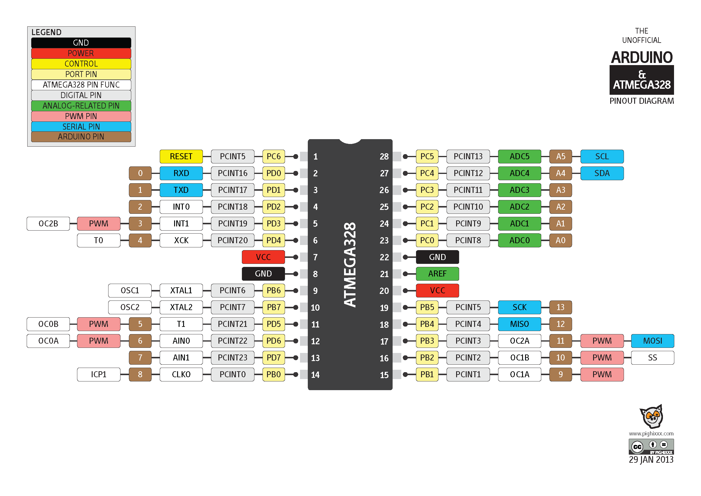

- #Arduino mega pinout chart how to#
- #Arduino mega pinout chart serial#
- #Arduino mega pinout chart software#
#Arduino mega pinout chart software#
To set an output pin high (3.3V) or low (0V), use digitalWrite(pin, value) where pin is the digital pin, and value either 1 or 0 (or HIGH and LOW).ĮSP8266 software PWM is supported on all digital pins. pin 5, use D5: for instance: pinMode(D5, OUTPUT) (*) NodeMCU uses a different pin mapping, read more here. To enable the pull-down resistor for GPIO16, you have to use INPUT_PULLDOWN_16. Just like with a regular Arduino, you can set the function of a pin using pinMode(pin, mode) where pin is the GPIO number*, and mode can be either INPUT, which is the default, OUTPUT, or INPUT_PULLUP to enable the built-in pull-up resistors for GPIO 0-15. GPIO16 has a built-in pull-down resistor. GPIO 0-15 all have a built-in pull-up resistor, just like in an Arduino. GPIO2 can’t be low at boot, so you can’t connect a switch to it.GPIO0 is pulled high during normal operation.You have to keep this in mind when using GPIO15 as an input to read a switch or connect it to a device with an open-collector (or open-drain) output, like I☬.

#Arduino mega pinout chart serial#
GPIO 1 and 3 are used as TX and RX of the hardware Serial port (UART), so in most cases, you can’t use them as normal I/O while sending/receiving serial data.įew I/O pins have a special function during boot: They select 1 of 3 boot modes: GPIO15 If you try to use one of these pins, you might crash your program. This is the small 8-pin IC right next to the ESP8266. The ESP8266 has 17 GPIO pins (0-16), however, you can only use 11 of them, because 6 pins (GPIO 6 – 11) are used to connect the flash memory chip.

In many application we need to connect 5V circuits with ESP8266 this can be achieved with use of simple resistor and diode as shown in below. The maximum current that can be drawn from a single GPIO pin is 12mA. The pins are not 5V tolerant, applying more than 3.6V on any pin will kill the chip. These digital input/outputs operate at 3.3V. Just like a normal Arduino, the ESP8266 has digital input/output pins (I/O or GPIO, General Purpose Input/Output pins). NodeMCU pins are confusing with actual numbers on the board.ĭon’t confuse your self seeing lots of pins on NodeMCU, having too many IOs. ESP8266 NodeMCU Pin Description NodeMCU Pinout Its small size makes it perfect for controlling of electrical appliances (IoT). use of this IO lines will crash the ESP prgram. Never use SPI IO Lines present on bottom side. Programming and functioning of all three devices is same.ĮSP8266 (NodeMCU) vs Arduino UNO Specificationīefore we start on GPIO programming of ESP8266, let’s see pinouts of each type.

Difference between ESP12, ESP01 and NodeMCU is only of Flash memory and Number of IOs are available to user. To get serial and IOs expantion like Arduino you can use NodeMCU. ESP8266 itself is very powerful microcontroller. Use of ESP8266 as just a Serial-to-WiFi bridge with arduino is most common mistake newbies do.
#Arduino mega pinout chart how to#
In this tutorial we focus only on GPIO pins of ESP8266 and How to use efficiently ?ĮSP8266 comes in many variants most popular is ESP-12 and ESP-01.


 0 kommentar(er)
